The Bolton Group
Several of our group were interested in wide-field imaging and therefore required a portable camera tracker. The only ones on the market are expensive and we wanted:- 1. More than 2 hours of tracking - and not having to wind back. 2. The constant rate of a worm drive - straight threaded rod drives have a non constant drive rate. 3. The camera to be mounted equatorially and certainly not using a ball & socket head.. Our drive solution uses a small worm and wheel with a direct stepper motor drive ie no intermediate spur gears. A worm gear with 180 teeth was suggested and this therefore required a stepper driving at 1 rev per 7 mins 59 seconds. To test the principles and performance a prototype was first built. |
 |
Prototype
For the prototype a very old Astro Systems camera tracker was used. The electronics and drive for this were no longer working so it provided a convenient test bed. There were obviously two strands to this project: 1. The mechanical construction and 2. The electronics.
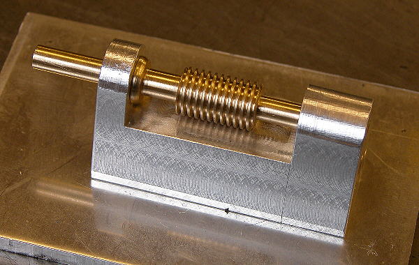
1. Construction
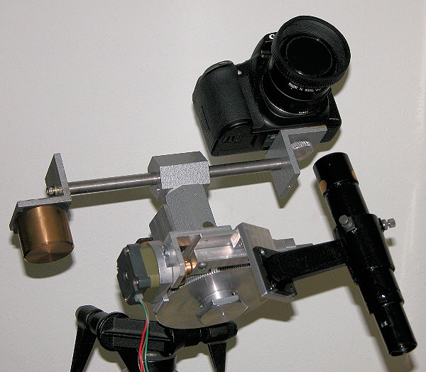
Brian made a worm and wheel to fit on the bottom of the existing RA axis and a motor coupling. The worm wheel has a simple manual clutch to facilitate easy movement around the sky and also to be able to release the drive to check for balance. This design has hole through the polar axis plus a separate polar finder telescope. The finished version will have the finder in the polar axis but this was not possible on the prototype.
2. Electronics
The group is fortunate in having an electronic expert (Ross) who was able to design, program and produce a circuit for driving the motor at the exact rate (1 rev per 7min 59sec). A low cost four wire bipolar stepper motor (HS31) with 1.8 degree step was purchased from Distel. This proved to have sufficient torque to drive even an out of balance camera.
Results:
The following is a small segment at full resolution from a 307 second unsharpened raw image taken with a 135mm lens and Canon 20Da. The target was near the celestial equator where drive errors would be most evident. Note unless a test image is shown at 1 pixel = 1 pixel (as here) then it is difficult to assess quality. When images are rescaled to fit a screen then they can hide all manor of defects.
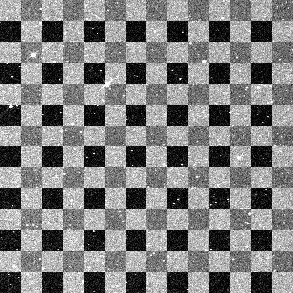
The following is a deliberately trailed image (polar axis offset) to measure the drive accuracy and periodic error over one cycle of the worm. Again a 135mm lens was used. As to be expected there is a small amount of periodic error but it is seldom more than the width of a bright star. The production gears will be brass which is easier to machine with high accuracy.

Production model Camera Trackers
Brian has completed the construction of 5 trackers. The design is much neater and more compact than the prototype. It does not use a Dec shaft like the prototype but still mounts the camera equatorially so north will always be vertical - there's nothing worse than a constellation image with north at a random angle.
The worm blocks are aluminium and the worm gears brass.
Below is the first worm wheel to be made. The large bore is to accommodate bearings with a sufficient bore for a polar finder scope.
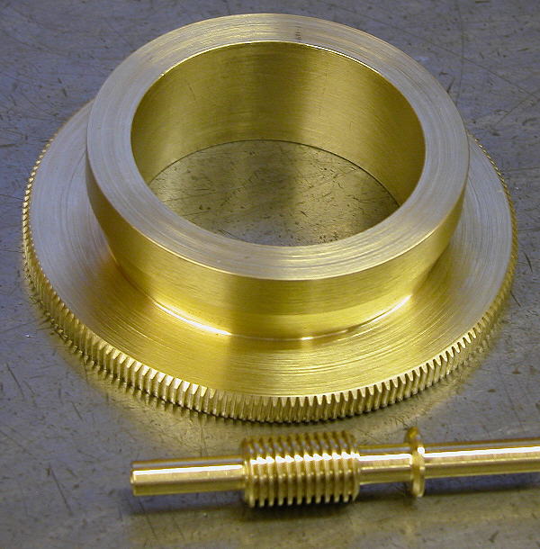
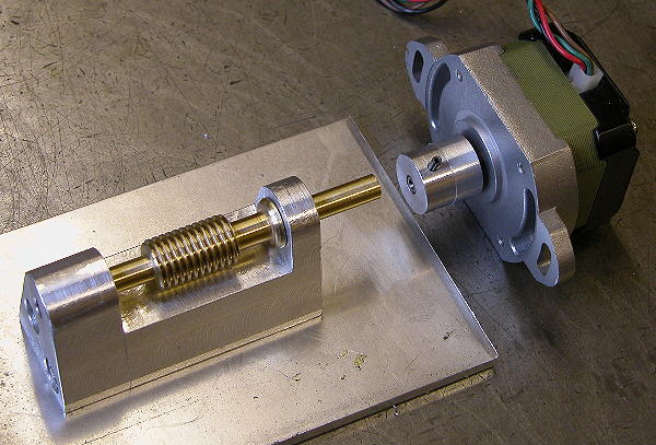
The stepper motor will be coupled direct to the worm shaft - no intermediary gears.
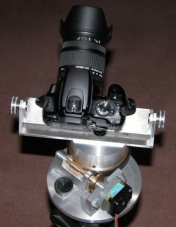
Below is the finished production model - one of 5 made. The camera is held in a mini-fork mount. Note how this is offset to the left (east) so as to put it slightly out of balance so the drive is working "uphill". The knob below the worm is to allow it to disengage completely from the wheel to check the balance. For moving around the sky the RA shaft has a clutch (inside the aluminium casing above the worm wheel).
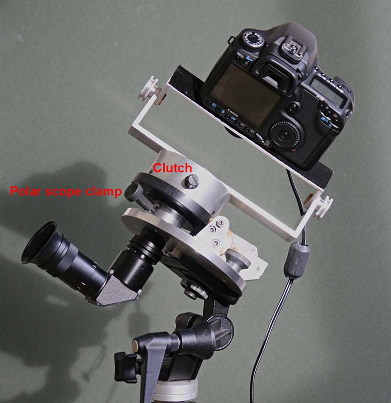
A recent addition is the right-angle polar-scope. Makes life much easier. An old pentacon camera right angled viewfinder was used.
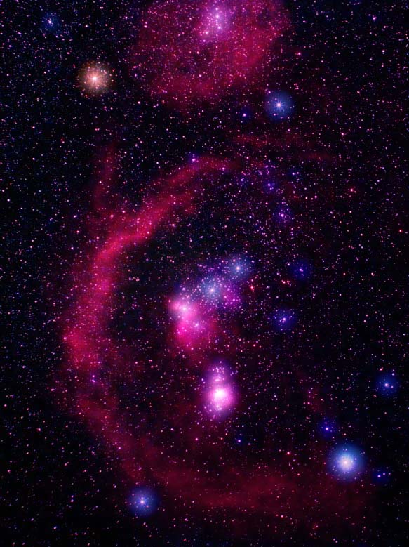
Below was shot with a Canon 300D and Pentax 50mm lens on the tracker.
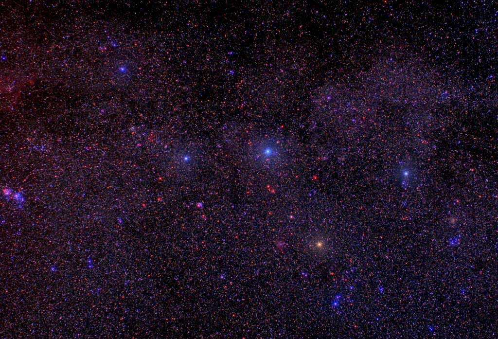
Orion with the tracker.