by The Bolton Group
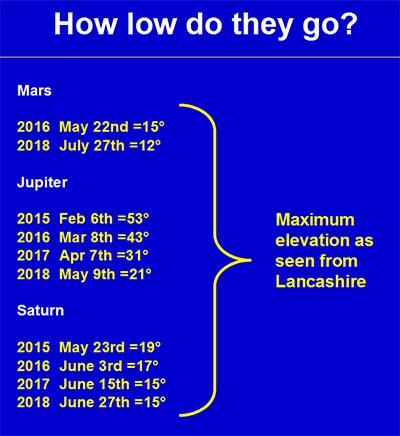
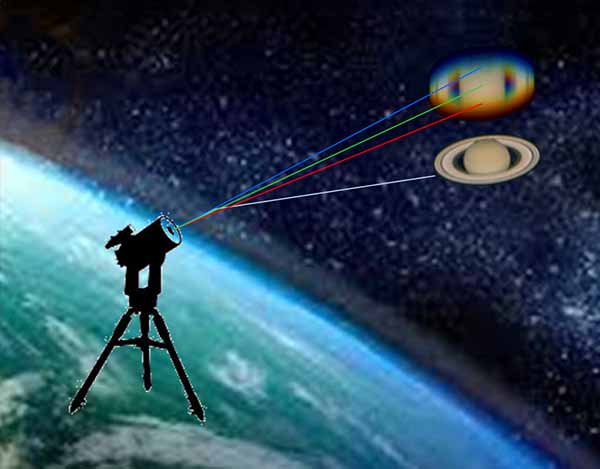
For the next several years the planets will be seriously low in the sky - at least from Lancashire. This means excessive atmospheric dispersion rendering imaging almost impossible. It will be like imaging through a prism!
If only there was something that could cancel out that dispersion. Well there is - it's called an ADC. It's not new - Horace Dall developed one over 50 years ago - so don't emigrate just yet. Professional observatories usually have one somewhere in their optical train and so can we.
You might think software can re-align the colour planes/channels but the dispersion
is within
the colours too - they are not single wavelengths.
Commercial ADCs are available and cost from £300. They generally use a pair of rotating prisms to introduce an equal and opposite dispersion that cancels out that due to the atmosphere. This simple type has undesirable side-effects but there is at least one more complex design on the market with 2 pairs of prisms with different glass types. This can produce the cancelling dispersion without the side-effects but the snag is they cost over £3000. However, there is an alternative that is easy to build and use.
Note: The type of ADC described here, using just 2 simple prisms, require long focal ratios i.e. f/15 or larger.
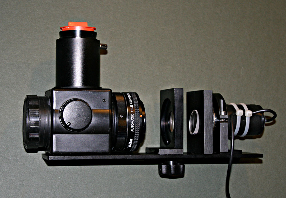
The finished unit. In use it has a lightweight plasticard cover.
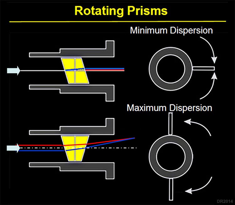
Rotating Prisms Design
Commercially available units - at least those at sensible prices - seem to be of this design with a pair of counter rotating prisms. Their big advantage is they require little back focus. They have two levers which must be rotated equally and oppositely to vary the dispersion - levers together for minimum dispersion and levers apart for maximum. They have 2 drawbacks (1) the amount of rotation must be determined by trial and error. If you have ever tried focusing a planetary image than you can guess how hard this is going to be! (2) Rotating the prisms shifts the image - quite probably off the ccd. In fact these pairs of prisms (known as Risley Prisms) are used to steer laser beams - the deflection produced by them enables targeting of the beam.
1. Compact
2. Image is displaced and skewed (varying amount)
3. Amount of prism rotation has to be a subjective judgement
4. Image is an off-axis image from the telescope.
5. Likely to be a frustrating experience with adjustment probably shifting the image off the chip!
I would guess many of these have ended up in the bin! Adjustment is fiddly - every adjustment producing an image shift. To counteract the image displacement, an off-axis image must be used - more distortion. The dispersion might have gone but new problems have appeared.
Note: An article in the British Astronomical Journal (2012) has a diagram purporting to show how this type works. The light paths shown are not correct with blue rays refracted in the wrong direction! This type displaces the image the more they are rotated - even the null position has a small displacement.
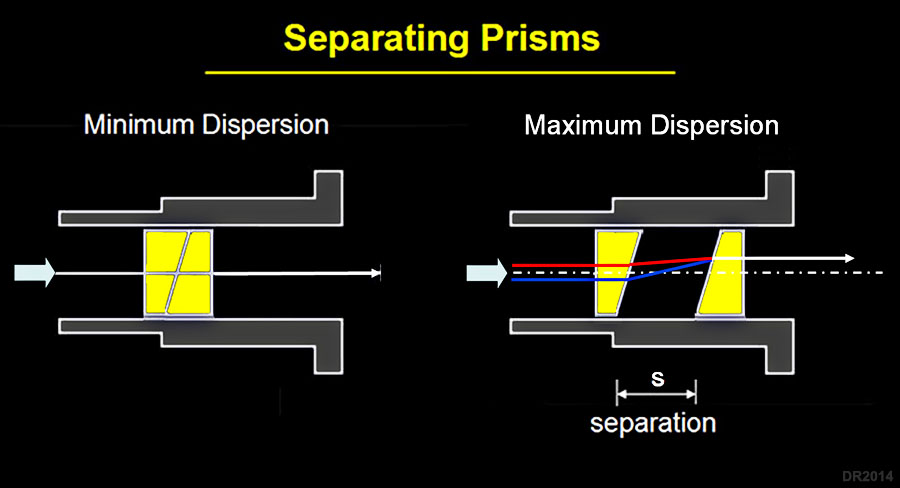
Separating Prisms Design
This design is used on the Keck Telescope - their prisms are 1 metre in diameter - ours can be 1 inch!.The drawback is that we will require more back focus i.e. space between the barlow lens and the ccd chip. The advantages far outweigh this issue. Instead of trial and error to find the cancelling dispersion we can now pre-calculate it. There is again an image displacement but this time it is vertical & parallel so we can raise the camera to accommodate it..
1. Not as compact as rotating design
2. Image is shifted vertically but remains parallel
3. Separation and vertical shift can be calculated and pre-set
4. Raising the camera means image is still an on-axis image from the telescope and is square
5. Flip mirror then retains alignment with ccd
6. Likely to be much less frustrating!
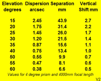
The above values are for my focal length (4 metres) and using 4 degree deviation prisms. The latter actually have an angle of about 7.7 degrees. The dispersion values above are for the difference between blue and red and are derived from a graph by Jean-Pierre Prost . I have consulted other available graphs and the figures are actually a bit of an average. The formula for separation is by Robert E. Majewski (ATT July-August 2014) . However, he doesn't calculate or correct for the upward displacement of the image - this really shouldn't be ignored especially for altitudes below 40 degrees.
Note: This design needs sufficient back focus. If this is a problem then consider 6 degree prisms.
Construction of a Separating Prisms ADC
The idea was to build the unit onto the back of a Vixen flip mirror finder. This would provide a square and secure platform to which the various components could be mounted. The prisms are available from ThorLabs . A pair of 4º Beam Deviation ones were ordered and mine came with a box of goodies!
For the design to work we need a method of moving one of the prisms and someway of raising the camera/webcam. The movement of one prism was easy enough - a slot and a thumbscrew. A pair of lugs under this plate keeps the movement square - Brian's invention. For raising the webcam I opted for a selection of shims - a bit crude but it keeps it simple. So when imaging the separation and vertical shift is read off the above spreadsheet printout and the ADC set ready for the imaging session.
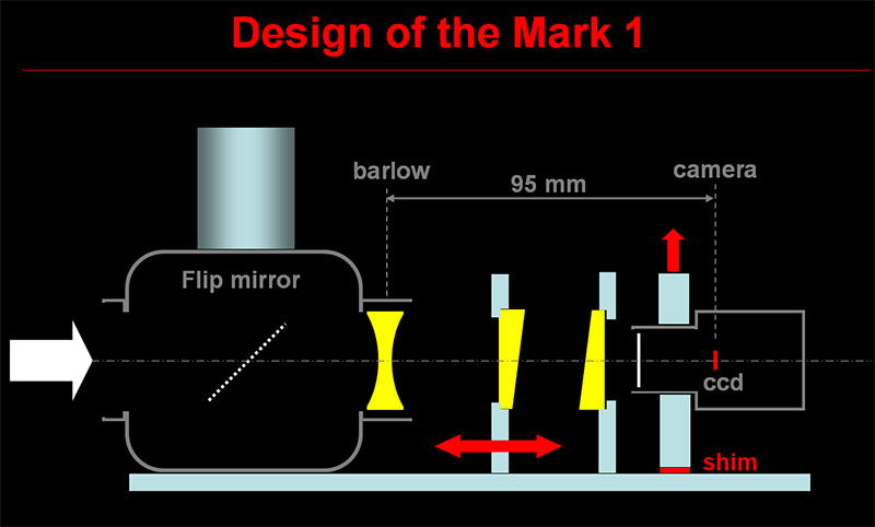
The biggest issue was getting enough room between the barlow lens and the CCD chip. The design I ended up with provides for up to 46 mm of prism separation which should be enough down to 15 degrees of elevation. The barlow lens is actually a 1.5x teleconverter which, when placed 90mm inside focus, acts as a 2x multiplier. Note this distance is actually for an air gap - because we have around 8 mm of glass in there then the distance needs increasing to around 95mm. I will need to measure the actual focal length though to confirm the calculations.
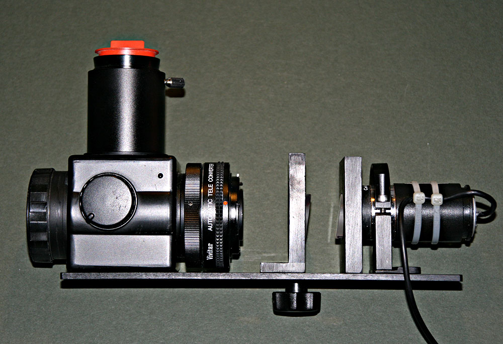
Unit after anodising. - note one 2mm shim is in position raising the webcam.
The unit was made by Brian and as can be seen is very logical. The flip mirror finder was drilled and tapped to carry the supporting bottom plate. The unit was later black anodised by Steve Read, another member of Bolton AS. The prisms are secured into their pockets with dabs of silicone. A lightweight plasticard shield covers the unit when in use.
Conclusion
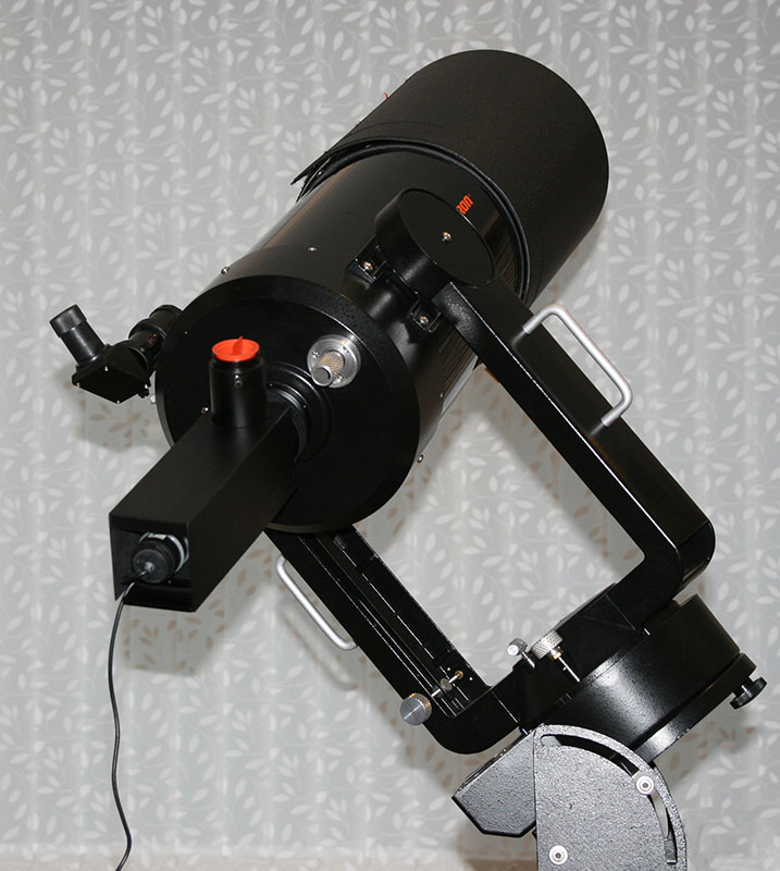
The finished unit mounted on my venerable C8. Note the orientation - it must always be kept vertical.
Does it work? The formulae I used came from one website and the dispersion graph from another. What could possibly go wrong? I have confidence in the design - it is used on the Keck telescope after all - so it should work but perhaps the precise prism separation may need refinement. If a multi-coloured Saturn appears in my image blog then you will know more research is needed.
First Tests
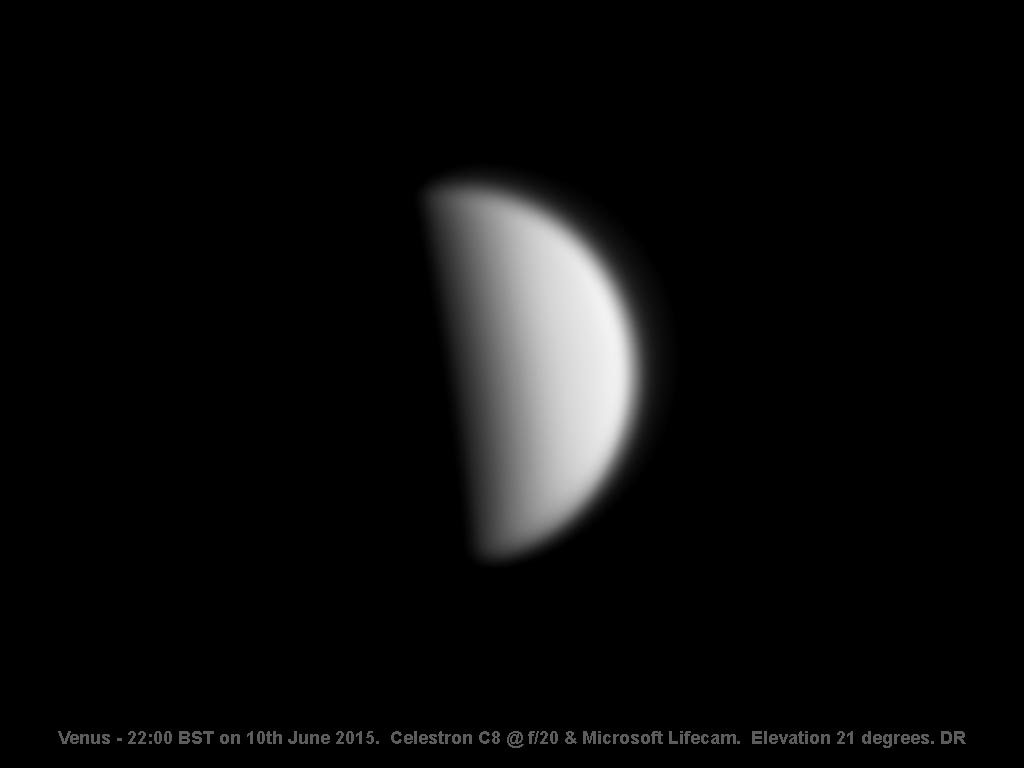
Below is the first image taken with the ADC. The altitude of Venus was around 21 degrees and the prism spacing set at 30mm. There was no re-alignment of the colour planes - this is as it came off the webcam!
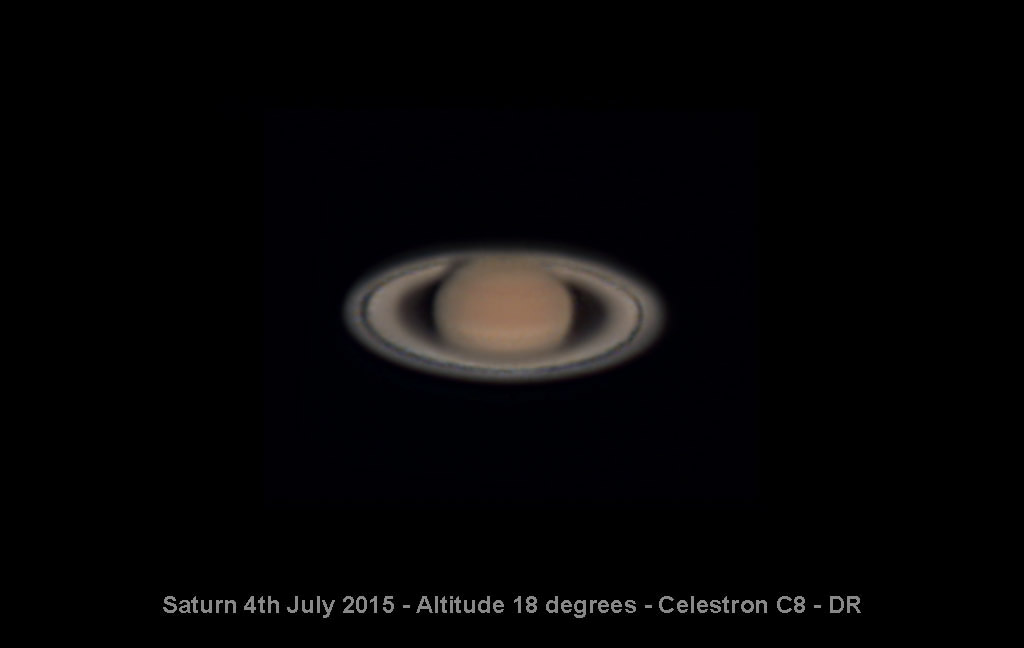
An even more severe test was Saturn at only 18 degrees of elevation. It's not a winner but it is amazing that, at this low down through the mushy Lancashire atmosphere, an image was possible at all. Again no alignment of the colour planes has taken place - in fact Registax was defeated when it tried to estimate the rgb error.