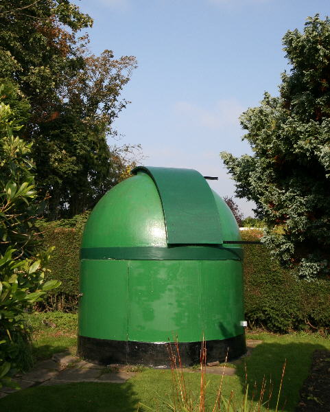
New Telescope and Mount 2007
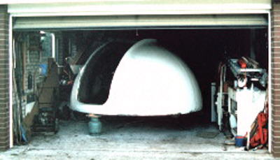
The Lancashire Observatory has undergone a complete re-fit with new telescope and mount. After a lifetime of homemade telescops and and mounts I finally succumbed to the lure of high-tech commercial equipment. The new mount is a Paramount ME and the main telescope an RC Optical Systems (RCOS) 12.5 inch f/9 Ritchey-Chretien.
The RCOS is a true Ritchey-Chretien cassegrain. This design uses 2 mirrors to produce a coma corrected field with no false colour. There is an option of closed carbon-fibre tube or open truss. For Lancashire with its damp climate and light pollution then the closed tube makes much more sense. The carbon-fibre tube also, having less aluminium, is less prone to temperature induced focus shift than the truss. The optics are in astro-sitall and were made by Paul Jones.
Ritchey-Chretien telescopes are often quoted as having a flat field which usually they are not. The flatness of field for a cassegrain telescope is almost entirely dependent on the ratio of the 2 mirror curves ie the magnification or amplification of the secondary - the bigger the magnification then the bigger the resultant field curvature. This is why f/10 Schmidt-Cassegrains with their 5x magnification have very curved fields. The amplification of the RCOS is 2.8x which makes for a longer tube than Schmidt-Cassegrains but much less curvature of field. All things being equal then the RC has a a slightly larger field curvature than other cassegrains.
Note not all Ritchey-Chretien are real ones! A well known manufacturer has in recent years tried to pretend that a coma-corrected Schmidt-Cassegrain is an advanced Ritchey-Chretien. They may be good telescopes but they are not Ritchey-Chretiens and secondary amplifications of 4 or 5 mean they are certainly not flat-field telescopes despite many dealers advertising them as such. They also have a small amount of chromatic aberration due to that Schmidt corrector lens. With modern CCD cameras sensitive well into the infra-red then chromatic errors are to be avoided.
Progress Report
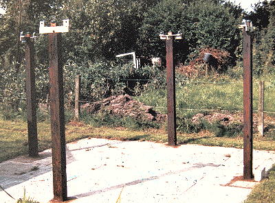
The old mount was sold in May 2007 leaving a big hole in the floor...............
The existing concrete foundation was retained and the idea was to construct on to it a new concrete plinth. This would in turn take a steel pillar for the Paramount.
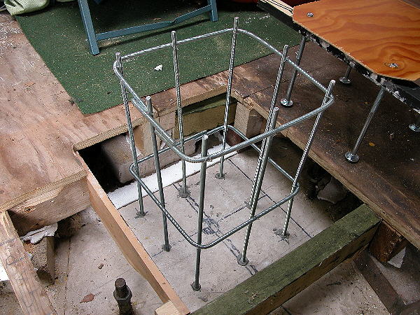
The existing concrete was drilled for 8 vertical reinforcing rods. They were epoxied into the holes. Reinforcing hoops completed the cage.
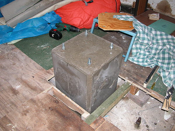
Formwork removed after 3 days. Still quite "green". It had been kept wet.
False floor repaired and carpeted. Concrete starting to go a bit whiter.
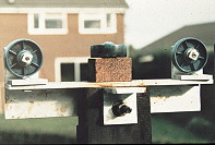
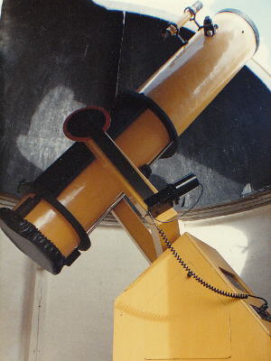
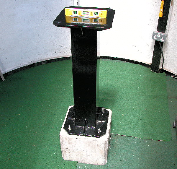
Pier dropped on. Fortunately the bolts were in the right place! Pier is made from 150mm RHS square section - 6 mm thick. Gusset plates add to the strength.
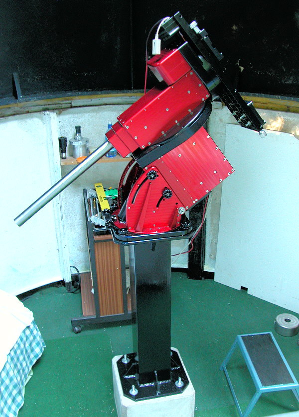
The Paramount has now been mounted in place. Next are the counterweights and then the two tube assemblies.
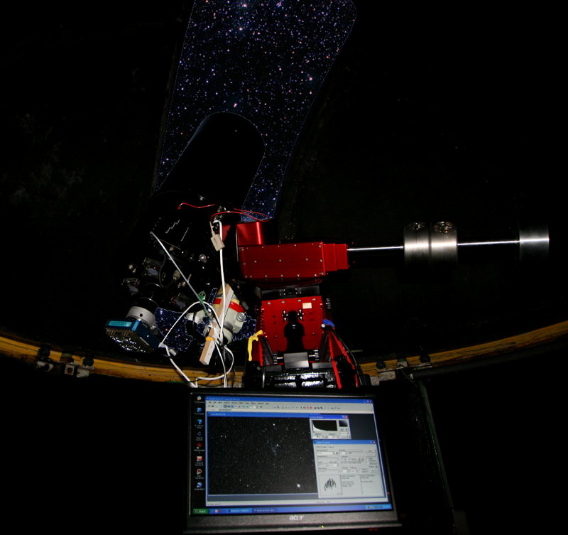
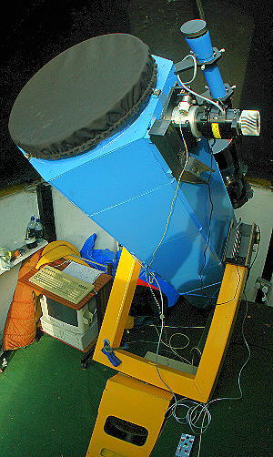
RCOS and Takahashi and their cameras mounted. Maxim takes control.
Polar Alignment
TPoint has been used for this. At first sight it looks difficult to master but, at least for polar alignement, it has proved relatively straight forward. The first run showed a large error in azimuth (0.7 degrees) but after one run of TPoint, with 20 mapped stars, this reduced to under 2 arcmins. A second run (35 stars) reduced this to even less. The aim was toset the polar axis 40 arcseconds high as this is suggested as ideal (for my latitude) for better tracking. This is the result:
This is the associated scatter diagram for the TPoint model:
Periodic error results:
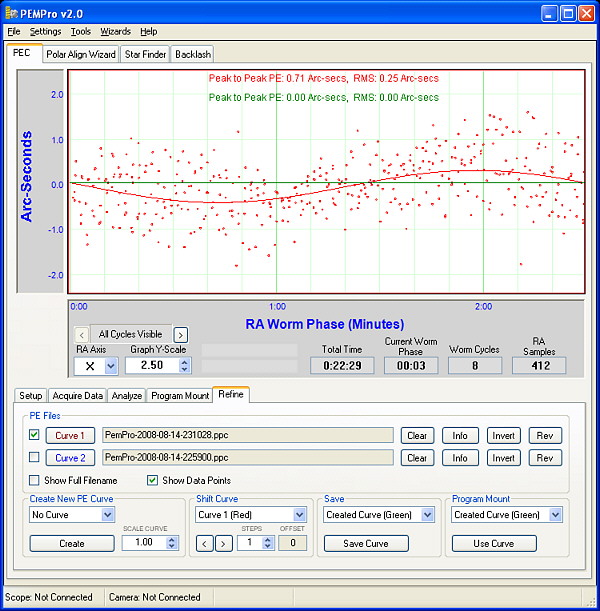
The periodic error is so small it is all but lost in the seeing noise.
CCD Camera
The camera I settled on was the Apogee Alta U9. This range boasts a lifetime guarantee on the chamber seal and as I have had problems with this in the past this seems just the camera for me. The chip I chose was the KAF-6303E. The size of this chip is 28mm x 18mm with 9 micron pixels. The quantum efficiency is very high at H-alpha (65%) and into the infra-red. I have to use light polution filters so efficiency away from the visual midband is important for me.
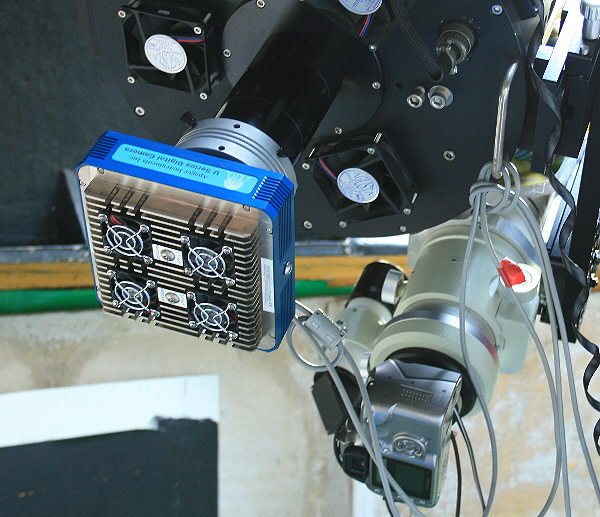
Currently work is progressing on getting it attached to the RCOS complete with off-axis guider. A Van Slyke Targetron is used but this has had to be modified to (hopefully) make finding a guide star easier. With the standard version I just could not centre a guide star.
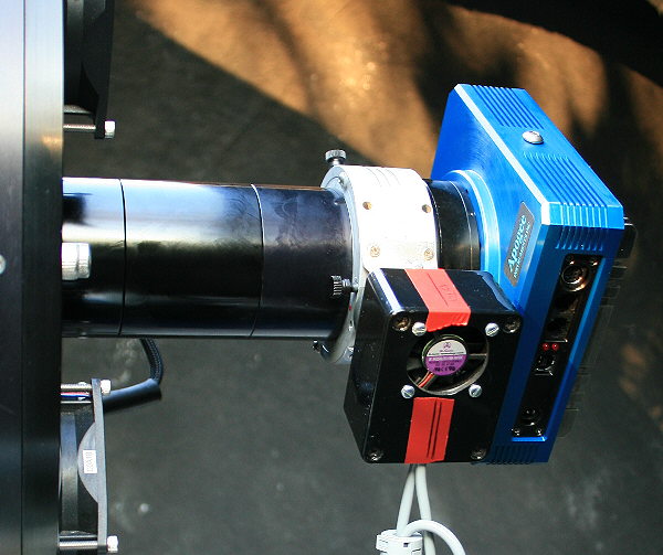
Webcam off-axis guider located ahead of the filter drawer. I tried the Opticstar PL130M autoguider but it behaved very oddly. Despite claiming 10 second exposures it actually recorded for 1.5 seconds then had a rest for 3.75 seconds and then another 1.5 seconds worth and so on! (test results here) Any exposure longer than 1.5 seconds is literally a waste of time. I am currently using a Starlight Xpress Lodestar which is very sensitive. It is however susceptible to electronic noise and its cable has to kept well clear of other power lines.
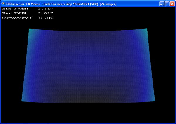
CCD Inspector curvature with Alta U9 (27.6mm x 18.4mm)
Remote Control
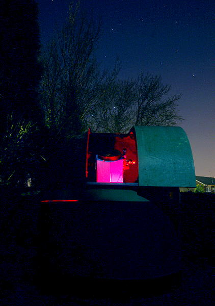
The telescope is operated remotely - well from 30 metres away in my (warm) house. The following should make it clear how this is achieved. 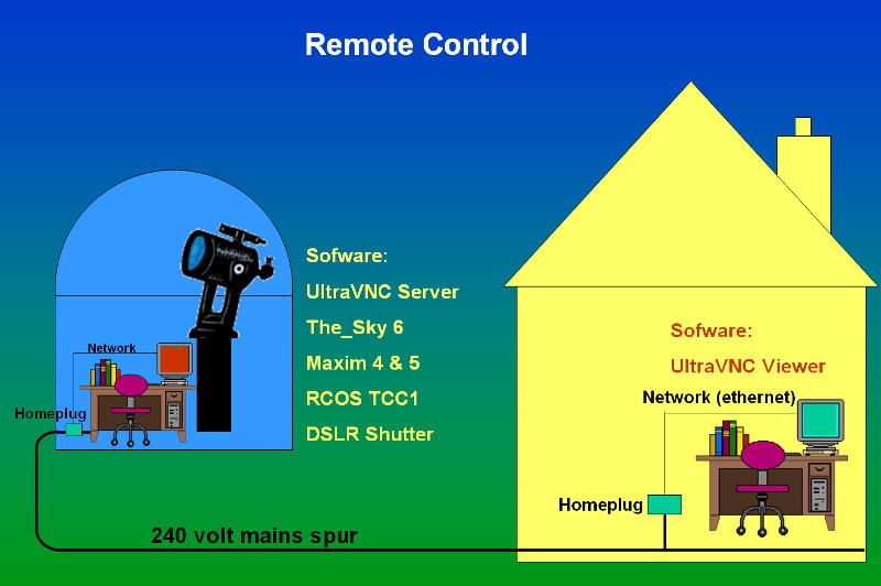
The observatory predates any thought of building-in ethernet connections so homeplugs have been used to get the observatory onto my house network. They work well but I found they don't like surge protectors so they are plugged in direct to the mains. UltraVNC handles the remote control and is very easy to set-up. It is magical watching images as they appear. As the images are taken they are copied over the network to the hard drive in the house thus satifying the rule that "digital images don't exist until they are in at least two places". I just need to get the dome motorised now for full remote control. |